
By Luke Berglind and Erdem Ozturk,
Researchers at the The University of Sheffield Advanced Manufacturing Research Centre (AMRC).
The primary objective of machining operations is to produce a final product that possesses a desired set of geometric features. In cutting operations, these features are produced by removing material from an initial stock of material until only the final part is left behind. To be successful, CNC machines must accurately position a cutting tool with respect to the workpiece so that only the correct material is removed (not too much, not too little), and the correct final part is produced. To achieve this goal, a great amount of work is dedicated to ensuring tool positional accuracy throughout machining processes.
In the Twin-Control project, our aim is to improve accuracy in the production of real parts by first generating parts virtually through simulation. By “producing” parts virtually first, it is possible to assess the accuracy of an operation and to make improvements where needed before any real part is produced (or scrapped). As is true for real parts, the virtual parts are generated by modelling tool motion, and virtually removing material based on the tool’s position. As such, how accurately a virtual part represents a real part is directly related to how accurately the tool motion is modelled in the simulation.
There are many factors which affect tool motion accuracy during a machining operation. In the Twin-Control project, the different partners are responsible for characterizing these factors based on their area of expertise. The University of Sheffield Advanced Manufacturing Research Centre (AMRC) is responsible for developing a process model so that displacements due to interactions between the tool and the workpiece in the machining process can be determined. Regardless of how well a machine can position a tool in space, once machining begins, force interactions between the tool and the workpiece will cause the tool to deflect relative to the workpiece and vice versa. The amount of deflection that occurs depends on many factors (workpiece and tool material, cutting tool, tool work piece engagement, tool stiffness, etc.). The process model currently under development at the AMRC will provide cutting force and moment information to Samtech throughout the operation so that the effects of these can be included when determining tool position during the operation.
The cutting forces acting between the tool and workpiece are determined in the AMRC module by first creating a virtual tool with the geometry of the tool used in the actual operation. An example virtual tool is shown in Figure 1A for a bull nose mill with three flutes and zero helix angle. Once the tool is created, a tool workpiece engagement map (TWE) is used to define which sections of the tool are or are not engaged in the workpiece for the current operation. As the tool rotates through this engagement zone, shown in red in Figure 1A, only sections of the engagement zone which the cutting edge is located will affect the cutting forces.
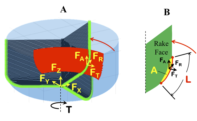
Figure 1: A) Cutting forces in the XYZ directions and spindle torque determined from cutting forces in RTA at the cutting edge and B) chip dimensions on the rake face used to calculate cutting forces.
Once the engagement region at the location of the cutting edge is determined, the resulting cutting forces are calculated using the following equations. These equations are used to determine the radial (FR), tangent (FT), and axial (FA) components of force based on the edge (Ke) and cutting force (Kc) coefficients, and the geometry of the chip created by tool engagement region (L and A).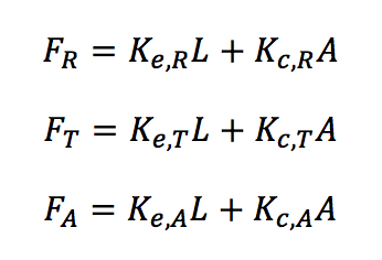 The edge and cutting force coefficients are obtained through experimentation for a given tool material and geometry, and workpiece material combination. These coefficients are used to determine forces in the RTA directions based on the cutting edge length of the engaged region, L, and the chip area, A, on the tool rake face (see Figure 1B). The edge length, L, is the length that the cutting edge is engaged in the workpiece, and the chip area, A, is dependent on the feed per tooth, and the orientation of the cutting edge.
Once L and A are determined, forces in RTA coordinates are determined at the location of the chip using the above equations, and then converted to forces in the XYZ directions and torque, T, as shown in Figure 1A. This process is repeated for multiple tool rotation angles to obtain cutting force and torque profiles for the current cutting operation, as shown in Figure 2.
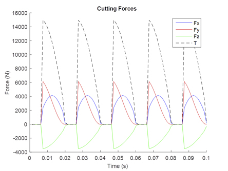
Figure 2: Example cutting force and torque profiles.
The cutting force and torque profiles shown in Figure 2 help us to understand how the cutting tool and the workpiece interact during the cutting process. Moving forward, our objective is to integrate these force interactions into the global machine simulation with Twin-Control partners. This will allow us to build a more complete picture of the machining operation, including information about part accuracy, surface quality and energy consumption; so that the machining operation can be verified before a real part is produced.
About AMRC
The University of Sheffield Advanced Manufacturing Research Centre (AMRC) is a world-class centre for advanced machining and materials research for aerospace and other high-value manufacturing sectors. It is a partnership between industry and academia, which has become a model for research centres worldwide. It has around 80 industrial members, from global giants such as Boeing, Rolls-Royce, BAE Systems and Messier-Bugatti-Dowty, to local small businesses.
The University of Sheffield AMRC is represented by the Machining Dynamics Technology Group in the project. The group performs research and develops methods to predict, diagnose and control machining vibrations and applies these results on industrial applications. The research themes of the group are predictive models, spindle dynamics, workpiece dynamics, vibration control, robotic and robotic assisted milling, composite milling and micro milling. The group also provides service to industry in the areas of process optimisation, benchmarking and training.