
By Jean-Pierre Delsemme, Frederic Cugnon and Hugues Legardeur
J-P. Delsemme is Software engineer and product manager at SAMTECH SA, a Siemens company
Frederic Cugnon is Flexible multibody dynamics expert at SAMTECH SA, a Siemens company
Hugues Legardeur is Product Manager at SAMTECH SA, a Siemens company
Industrial machines are more complex than ever. In an increasingly competitive market, companies must ensure innovation and manage complexity. Siemens PLM Software can help you build the right product, and build the product right.
Machinery manufacturers must employ advanced multi-disciplinary techniques and move from a serial development process to deliver designs that meet or exceed customer expectations. They must also ensure that all downstream design implications (CNC, commissioning) are considered during the early stages of product development to meet challenging time-to-market demands.
Providing realistic virtual simulation
Throughout the entire computer-aided engineering (CAE) design process, engineers have to optimize and carefully balance a variety of critical performance aspects. They need to verify and validate if the product under development will work as intended. This complex task cannot be one of test-and-repair. This would lead to endless expensive iterations on physical hardware. And some projects are even so unique that the first prototype is the final product. Testing that kind of product under extreme boundary conditions can have dramatic consequences.
Siemens PLM Software solutions for simulation provide engineers with all necessary tools to do upfront analysis for a variety of applications at every step of the process. To be successful, Machinery manufacturers must use models to reproduce the exact behavior of the real Machine in its operational environment, including all its complexities. Engineers require pinpoint accuracy to fully understand how a structure will work so they can expedite the analysis of a new design for potential modifications that can optimize performance.
The right solution for any nonlinear application
Samcef Nonlinear Motion Analysis fully exploits the augmented Lagrangian method and the large-displacement-large-rotation approach. The software features an extended library of rigid and flexible kinematic joints that can be included in FEA. As such, by coupling those joints to superelements and beams, the complete kinematics and dynamics of a system can be simulated through FEA.
When combined with Samcef Nonlinear Structural Analysis, nonlinear and fully meshed components can be included, capturing the complete material and geometrical nonlinear structural behavior.
On top of that, Samcef Nonlinear Motion can be used to integrate sensors, actuators and controllers in simulation. Those can be imported from Matlab®/ Simulink® and Imagine.Lab Amesim™ software or preprogrammed in Samcef. In that case, the controller parameters can be optimized. Samcef can also be coupled to Matlab and Amesim for co-simulation. This co-simulation capability of the solver is done through a dedicated module that enables the coupling between different transient solvers. This mechanism is used to connect Samcef to the AMRC’s tool that provides the cutting forces of the machines.
The implication of Samtech in Twin-Control
In the Twin-Control project, our focus is set on the dynamic modeling of the machine tool including its Computer Numeric Control (CNC), and its interaction with the machining process. To properly simulate modern high-speed machine tools, which show close interaction between the dynamic behavior of the mechanical structure, drives, and the CNC, it is crucial to build models that represent the flexibility of all components and their interactions.
Samcef Mecano enables accurate modeling of the machine by considering FEA models of the components connected together by a set of flexible kinematical joints. Particular models are implemented to deal with drive-trains and motors dynamics. To fully capture the dynamic behavior of the machine tool, force interactions between the cutting tool and the work piece are also considered in the models. Those forces take into account the dynamics of the tool tip combined with the tool work-piece engagement determined from Module Works CAD/CAM for toolpath generation and simulation. Coupling scheme is shown on figure 1.
A model of the CNC is connected to the machine model by the means of a specialized element that compute the motor forces from controller inputs, calling a dynamic library embedding the Matlab Simulink model of this controller.
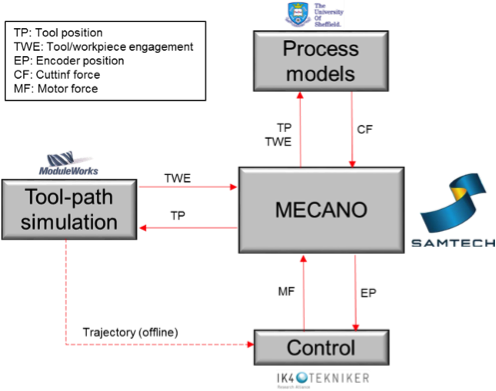
Figure 1. Coupling scheme
To model properly the machine tools when operating, the following objectives are followed:
- Account properly for the flexibility of all structural components, connections and feed drive to obtain a model that is able to represent vibrations inside the machine. The guiding system is modelled by flexible slider elements, which constrain a node to move along a deformable trajectory represented by beam elements.
- Limit the number of degrees of freedom (DOF) as small as possible to use the model in the time domain (small time step imposed mainly by the machining simulation module and the controller model). This is done by using the super-element technique. The modal contains of those super-elements is such that vibrations up to desired level could be represented.
The proposed technology is applied to build a mechatronic flexible multibody model of a box-in-box fast machine of COMAU. This approach allows providing comprehensive simulations capabilities for virtual machine tool prototyping in working conditions.
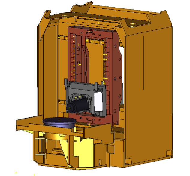
Figure 2. Multibody model of the Comau machine tool
The second example that illustrates this technology is a 5 axes machine from Gepro.
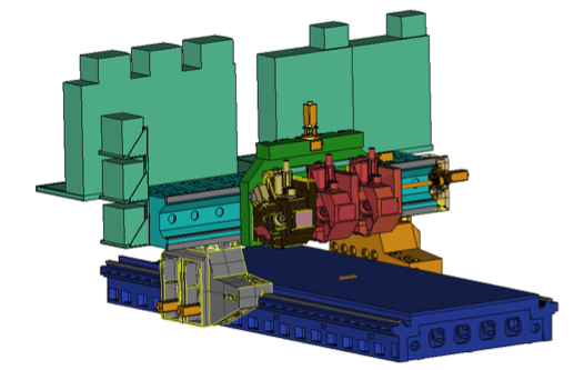
Figure 3. Multibody model of a five axes machine tool with multiple spindles
A Fagor CNC controls the motors of the different axes to follow the desired trajectories with minimum error. In the model, all frames are fully flexible, as the rails and screw drive trains, which are represented by sets of flexible slider elements. The control loops are modelled in MATLAB/Simulink, translated into a dynamic library that is associated to a specific control element used to manage the coupling between 1D models and the full flexible 3D model. Cutting forces are computed as in the previous model.
The resulting Twin-Control simulation package is dedicated to both machine tool builders for design activities and to machine tool users to improve their processes. In both case this virtual model will avoid performing many costly physical tests.